neděle 23. prosince 2012

Baofeng UV-3R in packet world using ArduinoTNC

Since it is so cheap and works reasonably well for 2m/70cm band in FM mode, I wanted to test also it's capabilities as FM modulator for AFSK digi modes and APRS.

First I needed a cable to connect to the radio. Fortunately that is relative easy and requires only four ring 3.5" jack and some standard components.

The cable pinout is easy:

Baofeng UV-3R TNC cable

To get to the packet world a TNC is needed. I was experimenting with different software solutions (soundmodem, agwpe), but this test was done with Arduino based TNC (because I had one laying around and it has USB to serial chip on board).

ArduinoTNC shield and cable


The design is based on KI4MCW's, but the software was updated to work well with latest BertOS (2.7.0) and to support KISS escapes and command structure.

Arduino TNC schematics (the filter cap on PTT line is missing here)

You can also download the complete source codes (complete with configured BertOS).

The TNC was connected to Xastir running on Mac OS X with the proper settings - Serial KISS TNC, 19200baud, /dev/cu.usbmodem24311 and "Transmit now" was triggered.

The radio switched to TX mode and... stayed transmitting. Oops. RF noise induced enough energy on the unshielded Arduino to trigger the PTT optocoupler and keep it triggered.

All that was needed to remedy this was to connect one SMD ceramic 100nF cap between PTT line and ground.

With that done, I triggered Transmit now again and measured what happened:
  • Blue line (CH1) measures the PTT line on the PCB (pin 11/PORTB3)
  • Red line is the audio output of the simple DAC, measured before the pot
With STE turned on in the menu, the radio showed about 230ms PTT to TX delay and 300ms TX tail as you can see on the attached pictures (watch the RF induced noise on the blue PTT line).

TxDelay with STE on

TxTail with STE on

The TX tail was pretty long so I turned the STE (Tail tone elimination) function off and tried again:
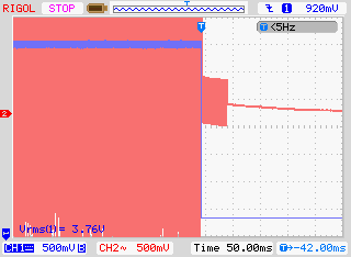
TxTail with STE off

With full power, STE turned off and resistance between the pot wiper and ground measured as 572 ohm the transmission was finally properly received by our local IGATE (9.2 km). So the UV-3R is indeed usable as an APRS transmitter.

pondělí 10. prosince 2012

My first foreign QSL card

I have just received a QSL card from Japan. It is my first QSL card from abroad and also my first satellite reception ever. :)


Not bad considering I have used the first version of FUNCube dongle and a corner reflector antenna mounted in the middle of the wall of an apartment building.

pondělí 27. února 2012

HF direct conversion receiver

Since I recently got my HAREC HAM licence, I decided I need a radio for HF. So here are a description and some pictures of the current contraption I use to listen on the 40m band.


The RX part was inspired by the popcorn DC receiver mainframe published by VE7BO on his site http://www.qrp.pops.net/popDC.asp. I used slightly different diplexer (similar to B variant) and created both filters with bistable relay switching circuit. ADE-1 from Mini Circuits serves as the main mixer.

DC receiver, groundplane construction,
the switch was later replaced by relay

The receiver used to be controled by Arduino (with Diecimila bootloader to support eeprom flashing), but has been since replaced by much smaller cpu board holding ATmega644PA microcontroller running at 8Mhz on internal oscillator. This board connects to all controls, LCD and a DDS box, which is the source of RF signal for the ADE-1 mixer in the receiver. The CPU board also provides 5V regulated power to all digital parts.

ATmega644PA with pin headers, voltage regulator (upper right)
and SFH5110-38 IR remote demodulator (bottom left)

A sample of AD9835 was used as a basis for the DDS oscillator, together with a low pass filter based on a design by maxit91 (http://hem.passagen.se/communication/dds.html). The whole module is built in RF tight box to prevent RFI.

DDS is the silver box next to the knobs.
You can also see the placement of LCD ad CPU boards,
power switch, fuse and back ground plane with connectors.

Filter switching relay is controlled using couple of transistors by two of the ATmega's pins.

Relay control board

There are four buttons, volume knob and rotary encoder for user input. Currently only volume, rotary and two buttons are used as the firmware still contains only very basic functions. It is possible to switch between CW and SSB filters and change the frequency (using 7 different steps from cca 1Hz to 1Mhz per revolution).

The insides.. just before the new CPU board was installed.

I will publish some schematics as I draw them as most of the work was experimental and the circuit changed often.

The current firmware lives at https://github.com/MarSik/HF-SSB-CW-direct-conversion-receiver including the bootloader that I had to adapt from Sanguino (m644p port) and Arduino sources (Diecimila's bootloader supports proper upload of eeprom data and reports correct signature).

In the future I'd like to use the free space I got by replacing Arduino to add CW transmit capability and about 5W PA.